


Description
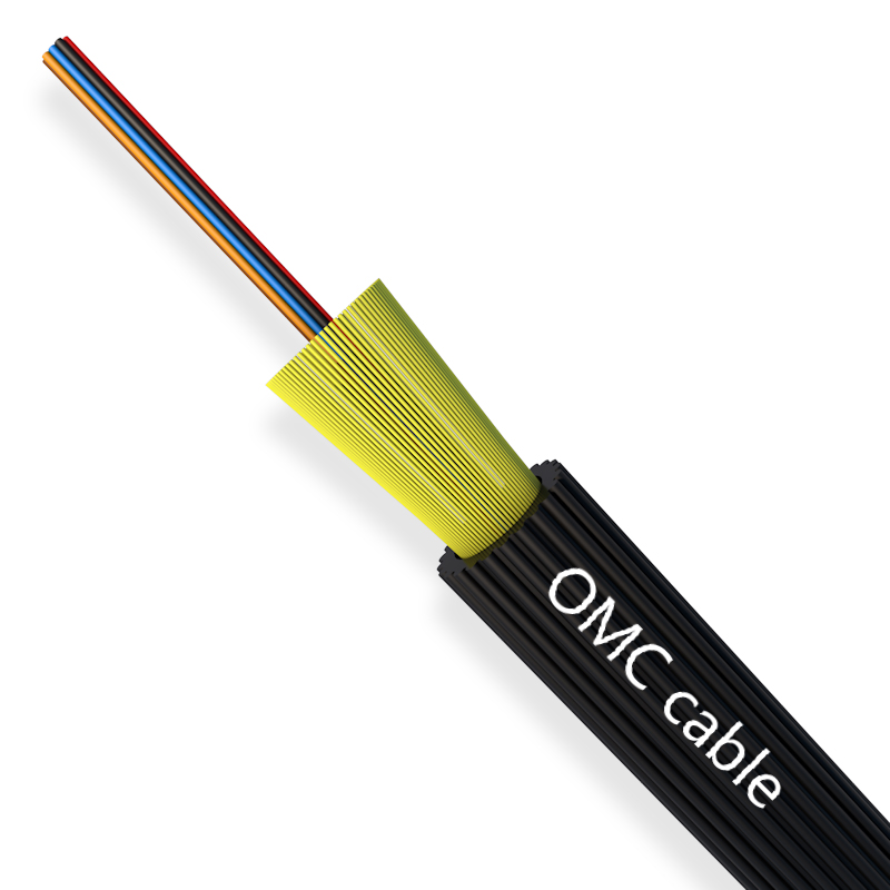
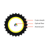
The 4-48F Mini Air blow Fiber optical cable, Also be called ABF cable. It consists of 4-48x 250um bare fibers, Those color-coded bare fibers covered by a layer of PE outer sheath.
OMC’s ABF Cable is with small diameter, lightweight, highly flexibility and proper stiffness. The fibres are coated with a soft acrylate resin which provides excellent dimensional and thermal stability to cushion the fibres, in addition, the resin can be easily stripped in connecting the fibres. The outer sheath is a thermoplastic that is of low friction. The surface of the sheath is designed with special grooves, compared to the surface of the traditional optical fibre cable, it provides not only the high level of mechanical protection, but also the perfect blowing performance.
Product structure parameters
| Project | unit | Parameter | |||
| Optical Fiber | Number | 6/12 | 24 | 36 | 48 |
| Strengthen the element | Kevlar | 1000D*9 | 1000D*12 | ||
| Cable Diameter | ±0.2mm | 2.8 | 3.5 | 4.0 | 4.5 |
| Cable weight | ±2Kg/km | 8 | 12 | 15 | 17 |
| Sheath material | LSZH or HDPE | ||||
| Sheath color | Black | ||||
| Sheath thickness | ±0.05mm | 0.5 | 0.6 | 0.6 | 0.6 |
| Long-term tensile strength | N | 400 | 400 | 400 | 400 |
| Short-term tensile strength | N | 1000 | 1000 | 1000 | 1000 |
| Long-term Flattening Force | N/100mm | 300 | 300 | 300 | 300 |
| Short-term Flattening Force | N/100mm | 1000 | 1000 | 1000 | 1000 |
| Static Bending Radius | mm | 15D | 15D | 15D | 15D |
| Dynamic Bending Radius | mm | 25D | 25D | 25D | 25D |
| Storage Temperature | ℃ | -40~70 | -40~70 | -40~70 | -40~70 |
| Install Temperature | ℃ | -10~60 | -10~60 | -10~60 | -10~60 |
| Run Temperature | ℃ | -40~70 | -40~70 | -40~70 | -40~70 |
Product standards :
Optical fiber:ITU-T G.657A2;
Air blow fiber: IEC 60794-5-20
Bend radius: IEC 60794-1-21, Method E11
Crush resistance: IEC 60794-1-21 Method E3
Kink: IEC 60794-1-21 Method E10
Tensile force during installation: IEC 60794-1-22, Method F1
Fiber parameters and tests according to the IEC series 60793-2 and 60793-1
Optical fiber technical parameters-SM
| Parameter | Conditions | Units | Value | |||
| G652D | G657A1 | G657A2 | G657B3 | |||
| Optical Specification | ||||||
| Attenuation | 850 nm | dB/km | – | – | – | – |
| 1300 nm | dB/km | – | – | – | – | |
| 1310 nm | dB/km | ≤ 0.350 | ≤ 0.350 | ≤ 0.350 | ≤ 0.350 | |
| 1383 nm | dB/km | ≤ 0.330 | ≤ 0.350 | ≤ 0.350 | ≤ 0.350 | |
| 1550 nm | dB/km | ≤ 0.210 | ≤ 0.210 | ≤ 0.210 | ≤ 0.210 | |
| 1625 nm | dB/km | ≤ 0.240 | ≤ 0.230 | ≤ 0.230 | ≤ 0.230 | |
| Attenuation vs. Wavelength | 1310 nm VS. 1285-1330 nm | dB/km | ≤ 0.04 | ≤ 0.04 | ≤ 0.05 | ≤ 0.03 |
| 1550 nm VS. 1525-1575 nm | dB/km | ≤ 0.03 | ≤ 0.03 | ≤ 0.04 | ≤ 0.02 | |
| 1550 nm VS. 1480-1580 nm | dB/km | ≤ 0.04 | – | – | – | |
| Zero Dispersion Wavelength | \ | nm | 1300-1324 | 1300-1324 | 1300-1324 | 1300-1324 |
| Zero Dispersion Slope | ps/(nm2·km) | 0.073-0.092 | 0.073-0.092 | 0.073-0.092 | ≤ 0.092 | |
| Dispersion | 1550 nm | ps/(nm·km) | 13.3-18.6 | 13.3-18.6 | 13.3-18.6 | |
| 1625 nm | ps/(nm·km) | 17.2-23.7 | 17.2-23.7 | 17.2-23.7 | ||
| Polarization Mode Dispersion (PMD) | ps/√km | ≤0.2 | ≤0.2 | ≤0.2 | ≤0.2 | |
| Cut-off Wavelength λcc | – | nm | ≤1260 | ≤1260 | ≤1260 | ≤1260 |
| Mode Field Diameter (MFD) | 1310 nm | μm | 9.2±0.4 | 9.2±0.4 | 8.6±0.4 | 8.6±0.4 |
| 1550 nm | μm | 10.4±0.5 | 10.4±0.5 | 9.6±0.5 | 9.6±0.5 | |
| Attenuation Discontinuity | 1310 nm | dB | ≤0.03 | ≤0.03 | ≤0.03 | ≤0.03 |
| 1550 nm | dB | ≤0.03 | ≤0.03 | ≤0.03 | ≤0.03 | |
| Bidirectional Attenuation | 1310 nm | dB/km | ≤0.04 | ≤0.05 | ||
| 1550 nm | dB/km | ≤0.04 | ≤0.05 | |||
| Geometrical | ||||||
| Cladding Diameter | μm | 125±0.7 | 125±0.7 | 125±0.7 | 125±0.7 | |
| Cladding Non-Circularity | % | ≤1.0 | ≤1.0 | ≤0.8 | ≤0.7 | |
| Core/Cladding Concentricity Error | μm | ≤0.6 | ≤0.5 | ≤0.5 | ≤0.5 | |
| Coating Diameter (Uncolored) | μm | 242±7 (standard) | ||||
| μm | 200±10 (optional) | |||||
| Coating/Cladding Concentricity Error | μm | ≤12 | ≤12 | ≤12 | ≤12 | |
| Curl | m | ≥4 | ≥4 | ≥4 | ≥4 | |
| Environmental (1550nm, 1625nm) | ||||||
| Temperature Cycling | -60℃ to +85℃ | dB/km | ≤0.03 | ≤0.05 | ≤0.05 | ≤0.05 |
| High Temperature &
High Humidity |
85℃, 85% RH, 30days | dB/km | ≤0.03 | ≤0.05 | ≤0.05 | ≤0.05 |
| Water Immersion | 23℃, 30days | dB/km | ≤0.03 | ≤0.05 | ≤0.05 | ≤0.05 |
| High Temperature Aging | 85℃, 30days | dB/km | ≤0.03 | ≤0.05 | ≤0.05 | ≤0.05 |
Optical fiber technical parameters-MM
| Features | Conditions | unit | Value | ||||
| OM1 | OM2 | OM2+ | OM3 | OM4 | |||
| Optical Characteristics | |||||||
| Attenuation | 850nm | dB/km | ≤2.70~≤3.00 | ≤2.50 | ≤2.50 | ≤2.50 | ≤2.50 |
| 1300nm | dB/km | ≤0.60~≤1.00 | ≤0.70 | ≤0.70 | ≤0.70 | ≤0.70 | |
| Minimum Modal Bandwidth | 850nm | MHz.km | ≥200~≥100 | ≥500~≥200 | – | – | – |
| 1300nm | MHz.km | ≥600~≥160 | ≥1200~≥400 | – | – | – | |
| Overfilled Launch Bandwidth | 850nm | MHz.km | – | – | ≥700 | ≥1500 | ≥3500 |
| 1300nm | MHz.km | – | – | ≥500 | ≥500 | ≥500 | |
| Effective Modal Bandwidth | 850nm | MHz.km | – | – | ≥950 | ≥2000 | ≥4700 |
| Numerical Aperture | 0.275±0.015 | 0.18~0.215 | |||||
| 10Gb/s Ethernet link length | M | – | – | 150 | 300 | 550 | |
| Backscatter Characteristics(1300nm) | |||||||
| Irregularities over fiber length and point discontinuity | dB | ≤0.1 | |||||
| Attenuation uniformity | dB | ≤0.1 | |||||
| Step (Mean of bidirectional(measurement) | dB/km | ≤0.1 | |||||
| Geometry Characteristics | |||||||
| Core Diameter | μm | 62.5±2.5 | 50±2.5 | ||||
| Core non-circularity | % | ≤5.0 | |||||
| Cladding Diameter | μm | 124.3±0.7 | |||||
| Cladding non-circularity | % | ≤2.0 | |||||
| Core/Cladding Concentricity Error | μm | ≤1.5 | |||||
| Coating Diameter | μm | 245±10 | |||||
| Coating/Cladding Concentricity Error | μm | ≤12.0 | |||||
| Delivery Length | km/reel | ~16.8 | |||||
| Environmental characteristics(850nm &1300nm) | |||||||
| Temperature dependence induced attenuation | -60℃~+85℃ | dB/km | ≤0.10 | ||||
| Temperature-humidity cycling deduced attenuation | -10℃~+85℃,98%RH | dB/km | ≤0.10 | ||||
| Water soak dependence induced attenuation | 23℃±2℃,30 days | dB/km | ≤0.10 | ||||
| Damp heat dependence induced attenuation | 85℃±2℃and85%RH,30 days | dB/km | ≤0.10 | ||||
| Dry heat aging | 85℃±2℃ | dB/km | ≤0.10 | ||||
Application:
Air blow fiber systems use air to blow micro optical fiber cables through pre-installed microducts.
Air blowing fiber, also known as jetting fiber, is an efficient way to install fiber optic cable and facilitates future expansion of optical fiber networks. Fibers can be installed in areas that are hard to reach or that have limited access. Air Blow Fiber is also recommended for environments where there will be many changes and additions to the network. It also allows for duct installation before you know how much fiber is actually required, and so eliminates the need to install dark fibers. It also reduces splicing and interconnection points so optical loss is minimized and system performance is enhanced.
The cable can be used as the drop cable of distribution segments in FTTH networks and can be laid by air blowing to connect the branch point with the access point for subscribers. The cable is also applicable in backbone networks , metropolitan area networks and access networks
Air Blowing cable technology is a new way to make significant improvements in traditional fiber optic systems, facilitating the rapid adoption of fiber optic networks and providing users with a flexible, secure, cost-effective cabling system.
The blowing system consists of micro-tubes (single micro-tubes and micro-tubes), micro-cables, fittings and air blowing equipment.
Featured Products


OMC’s 1F Toneable Flat Drop cable is a kind of...
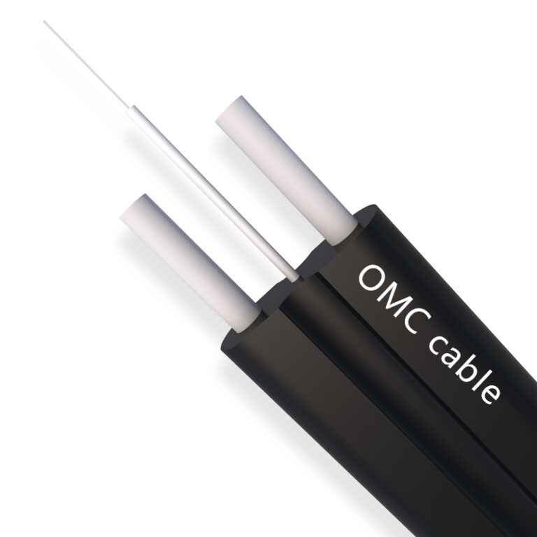
1F All Dielectric FTTH Flat Drop Cable -3.0×5.4mm...